15 Feb Fiber Optic Loss on Fiber Optic Cables
Fiber Optic Loss
Fiber optic loss is the reduction of optical signal power as light travels through a fiber link. It directly affects certification results, transmission stability, link distance, and the margin available between transmitter output and receiver sensitivity.
In practice, installers do not deal with one single source of loss. They deal with cable attenuation, mated connector loss, splice loss, bending effects, and the operating wavelength used by the active equipment. That is why the real question is not just “What is the loss?”, but “Is the total loss still inside the allowed optical budget?”
- Attenuation and dB basics
- Loss budget calculation
- Connector and splice impact
- Testing and acceptance logic
What Is Fiber Optic Loss?
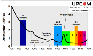
Fiber optic loss, also called optical attenuation, is the reduction of light power between the transmitting end and the receiving end of a fiber link. It is normally expressed in decibels, and for cable attenuation it is often written as dB/km.
Loss is not automatically a fault. Every optical link has some expected attenuation. The problem starts when total link loss exceeds the allowed limit of the cabling design, the target application, or the power budget of the active equipment.
The glass itself absorbs and scatters a small part of the optical signal as distance increases.
Every mated connector pair adds loss because alignment, end-face condition and cleanliness are never perfect.
Fusion and mechanical splices introduce additional attenuation depending on fibre alignment and splice quality.
Tight routing, poor storage loops and installation stress can force light out of the core and raise attenuation.
What Causes Fiber Optic Loss?
Most field problems come from the combination of several small losses, not from one dramatic failure. A link may pass visually and still fail on attenuation because the design quietly accumulated too many connection points, too much bend stress, or too little safety margin.
| Loss source | Where it appears | Typical field impact | What to check |
|---|---|---|---|
| Fiber attenuation | Over the full cable length | Higher loss on longer links, wavelength dependent | Fiber type, wavelength, link distance |
| Connector loss | Patch panels, adapters, equipment jumpers | Often the largest avoidable loss contributor | End-face cleanliness, connector grade, number of mated pairs |
| Splice loss | Fusion or mechanical splice points | Can accumulate quickly on long distribution routes | Splice quality, machine calibration, sleeve protection |
| Bend loss | Cabinets, trays, handholes, pulling points | Intermittent failures and inconsistent test results | Minimum bend radius, storage loops, routing discipline |
For installers working with blown fibre networks, bending and handling loss are often underestimated during route preparation. A badly planned path can increase attenuation even before the link is terminated. That is why practical route handling still matters alongside lab numbers. You can review related installation practice on our fiber optic blowing tips page.
How to Calculate Fiber Optic Loss
The cleanest way to estimate fiber optic loss is to build the full link budget before the installation is certified. In simple form, total optical loss is the sum of cable attenuation, connector loss and splice loss. In real projects, a design margin is usually added as well.
Fiber optic loss calculation example
Assume a 300 m single-mode link with three mated connector pairs and no splices. If cable attenuation is taken as 0.35 dB/km, the cable portion is 0.3 × 0.35 = 0.105 dB. If each connector pair is budgeted at 0.50 dB, connector loss is 1.50 dB. Total estimated link loss becomes about 1.61 dB before any extra safety margin is added.
Start with the real installed route length, not the nominal building distance. Slack, routing changes and panel access matter.
People routinely forget patch panels, adapters and intermediate cross-connect points, then act surprised when the test result is higher.
A link that only works on paper with zero margin is not a robust design. Aging, repairs and field tolerances exist whether humans enjoy them or not.
Acceptable Fiber Optic Loss Values
There is no single universal number that defines acceptable fiber optic loss for every installation. The correct limit depends on the cabling model being used, the application standard, the transceiver pair, the wavelength, and the number of loss-generating components in the channel.
Fiber optic loss based on cabling limits
This is the component-based approach used during certification planning. The expected loss is estimated from the fiber attenuation, connector count and splice count of the installed channel. It is useful when the future application is not fixed yet.
Fiber optic loss based on the application
If the application is already known, acceptable attenuation can be checked against the channel loss limit supported by that application. This is often more practical than quoting a generic dB number with no context.
Fiber optic loss based on transceiver power budget
When the active equipment is known, the most direct answer comes from the power budget. The maximum allowable loss is the difference between minimum transmitter output and receiver sensitivity, minus any reserve margin needed for reliable operation.
How Fiber Optic Loss Is Tested
Loss is normally checked during installation, troubleshooting or final acceptance. The two most common field approaches are insertion-loss testing with an OLTS and event analysis with an OTDR. They answer different questions and should not be treated as identical tools.
Measures end-to-end insertion loss directly. This is the normal method for link certification because it tells you the actual total attenuation of the installed channel.
Shows events along the route such as splices, reflections, breaks and localized anomalies. It is excellent for diagnostics but not a replacement for proper end-to-end certification.
- Inspect and clean connectors before the test. Dirty connectors create fake problems and waste time.
- Test at the correct wavelength for the installed fibre and application.
- Compare the measured result against the planned loss budget, not against a random number copied from another project.
- Use OTDR when needed to isolate where the excess attenuation is actually happening.
Why Fiber Optic Loss Matters in Real Installations
High attenuation does not always create a clean hard failure. Sometimes it creates unstable communication, lower operating margin, intermittent alarms, or links that pass at commissioning and fail later after small environmental changes. That is why optical loss should be treated as a design parameter, not just a test report number.
A link can fail acceptance even when the cable route is physically complete, simply because connector count and loss planning were handled lazily.
Excess attenuation reduces the usable reach of the link and narrows the margin available to the transceiver pair.
Bad loss planning usually comes back later as repeat site visits, connector cleaning, re-splicing or unnecessary equipment replacement.
For a broader commercial and technical view of why fibre remains the preferred long-term medium, see 11 reasons why the future belongs to fiber optic. For cable selection itself, the most relevant product group remains our fiber optic cable range.
Fiber Optic Loss FAQ
What is acceptable fiber optic loss?
What causes fiber optic loss the most in short links?
How do you calculate fiber optic loss?
What is the difference between attenuation and insertion loss?
Should OTDR and OLTS results be identical?
Why can a short fiber link still fail a loss test?
Useful links for fiber optic loss planning
OS1 and OS2 fiber optic cores
Fiber optic blowing tips
The future belongs to fiber optic
Fiber optic cables
Fiber optic dome closure
Power distribution unit
FOA loss budget reference
Fluke loss budget guide
Cisco attenuation calculation guide
Need the right fibre cable structure for your loss target?
Loss budgeting gets easier when the cable type, wavelength, termination method and route design are defined correctly from the beginning. Fixing attenuation after installation is always slower and more expensive than planning it properly before the first pull.