Fiber Optic Assemblies
Patch · Splice · Manage · Test
Build an optical link with compatible cables, connectors, panels and enclosures. UPCOM fiber optic connectivity products cover termination, cross-connection, high-density distribution and cable management.
Start with the fiber type, number of working fibers, equipment interfaces and loss budget. Then choose the termination method and installation format; a connector name alone does not define a complete optical link.
| Requirement | Product family | Define before ordering |
|---|---|---|
| Rack termination and patching | Fiber optic patch panels | U height, adapter format, fiber count, splice trays and loaded/empty configuration |
| Wall-mounted distribution | Wall patch boxes | Cable entries, splice capacity, adapter openings and available mounting space |
| Parallel optics or high-density backbone | MPO / MTP trunks and fanouts | Fiber type, active fiber count, polarity, pinned/unpinned connectors and mating loss |
| Convert trunk to individual connections | MTP to LC cassettes | Trunk pinning and polarity, LC layout, cassette chassis compatibility and loss budget |
| Protect splices at field joints | Dome and inline closures | Cable diameters, branch count, splice trays, installation environment and sealing method |
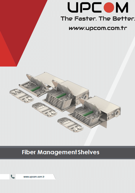
| Protect and route patch cords | Raceway, pathway and management shelves | Cable volume, allowable bend radius, routing path and future expansion |
| Prepare and verify connections | Fiber hand tools and test plan | Termination method, connector inspection, cleaning and end-to-end measurement |
Match singlemode or multimode fiber throughout the link. Specify OS2 or the required OM grade, connector polish and mating interface. UPC and APC ends require compatible mating components; do not select adapters by color alone.
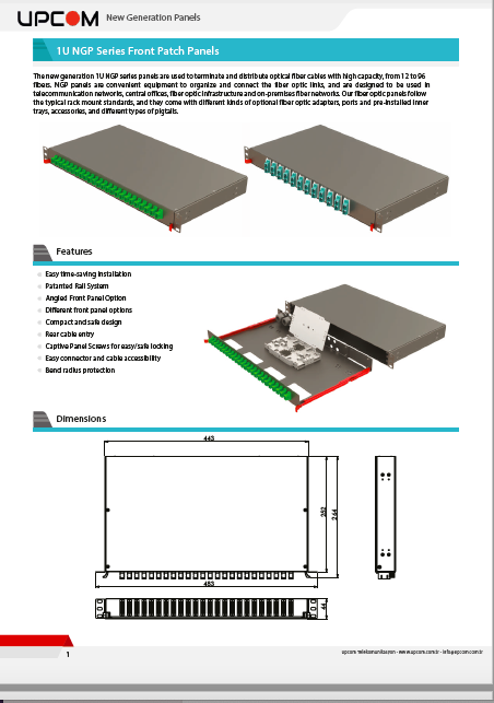
The NGP 1U catalogue distinguishes adapter openings from fiber capacity. Duplex and quad adapters can carry more fibers than the number of openings. The examples below belong to that specific panel family.
| NGP front panel | Openings | Compatible layout | Fiber capacity |
|---|---|---|---|
| NGP01 | 24 | SC simplex / LC duplex / E2000 simplex | 24 / 48 / 24 |
| NGP02 | 24 | SC duplex / LC quad | 48 / 96 |
| NGP03 | 12 | SC simplex / LC duplex / E2000 simplex | 12 / 24 / 12 |
| NGP04 | 12 | SC duplex / LC quad | 24 / 48 |
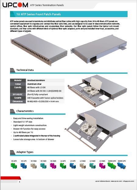
The ATP termination-panel catalogue separately describes a 1U anodized aluminum family for 24–48 fibers, supplied empty, partly loaded or fully loaded. Confirm the front panel, adapters, pigtails and trays included in the selected order code. Compare patch panel formats.
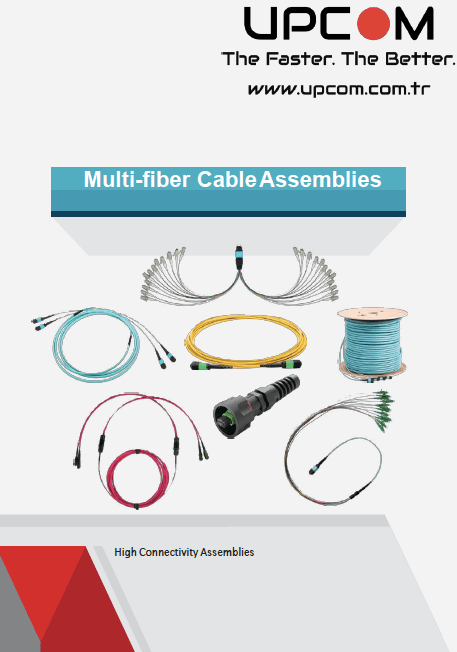
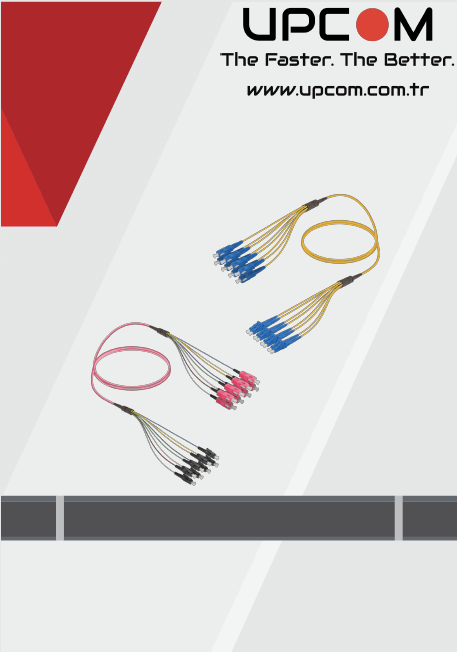
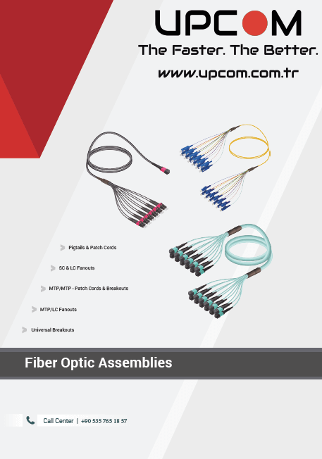
A trunk connects multi-fiber interfaces. A fanout separates fibers into individual connector legs, while a cassette provides a housed transition between interfaces. Choose the format to match equipment and maintenance access.
The MPO/MTP assembly PDF lists 8-, 12- and 24-fiber options with OS2, OM3 or OM4 fiber. LC fanouts are listed as 4, 6 or 12 duplex connections respectively. Specify polarity, male/pinned or female/unpinned ends, connector polish and required insertion loss for each end.
Include every mated pair, splice and cassette in the total optical loss budget. A low-loss connector option does not establish the loss of the entire channel. Review the MPO cable specification and ordering guide.
Use the corresponding PDF for model construction and ordering options. Confirm the exact configuration and current availability when requesting a quotation.