
Copper Connectivity Catalogue
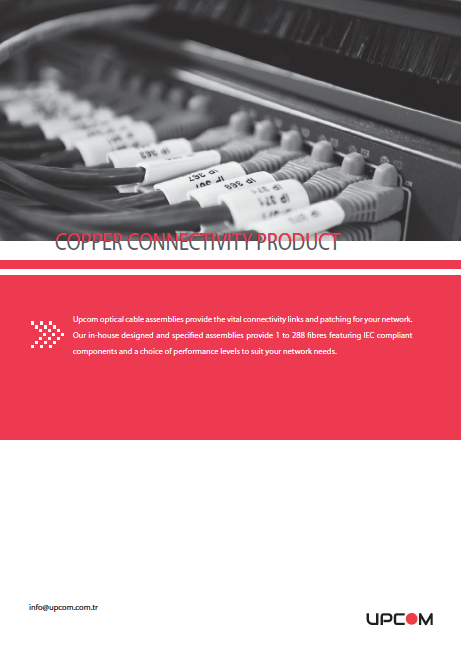
RJ45 connectors · Patch panels · Patch cords
Copper connectivity products connect balanced twisted-pair network cables to equipment and structured cabling panels. Select the cable, connectors, panel and patch cords as compatible parts of the complete channel.
Match category, shielding, conductor construction and termination method. The lowest-performing component and the installed workmanship can limit the resulting channel.
| Component | Role | Selection information |
|---|---|---|
| RJ45 plugs and boots | Cable termination and strain relief | Solid or stranded conductors, conductor/jacket diameter, shielding and category |
| Jacks and outlets | Fixed endpoint termination | Category, shield continuity, termination tool and pin assignment |
| Copper patch panels | Central rack termination | Rack U height, port count, punch-down or tool-less format and rear cable support |
| Copper patch cords | Connect panel to equipment or outlet | Category, shielding, flexible conductor construction, length and jacket |
| Cable pathways | Route and support cables | Cable quantity, load, bend radius, separation and expansion space |
The copper catalogue includes Cat5e 24-port 1U punch-down panels, Cat6 tool-less 24-port panel layouts and shielded variants. Confirm the particular model and included jacks. A modular panel chassis and a complete loaded patch panel are different order configurations.
| Category | Nominal category bandwidth | Project selection |
|---|---|---|
| Cat5e | 100 MHz | Match Cat5e cable, connectors and patch cords; verify the installed link |
| Cat6 | 250 MHz | Select Cat6 components and installation limits for the required application |
| Cat6A | 500 MHz | Use a compatible Cat6A channel and verify performance for the required network interface |
Bandwidth in MHz describes cabling frequency performance, not the network data rate in Gbit/s. Cable category alone does not certify an installed channel. Match shielding across cable and connecting hardware, and define the bonding arrangement for shielded systems.
Specify T568A or T568B consistently for the link and follow the connecting-hardware instructions. Confirm plug suitability for solid installation cable or stranded patch cable rather than choosing solely by its external appearance.
The Copper Connectivity PDF includes a Cat6A S/FTP patch-cord construction. These values apply to that catalogue example; other patch-cord models require their own specification.
| Parameter | Published example |
|---|---|
| Frequency range | Up to 500 MHz |
| Conductor | 24 AWG stranded copper, 7 × 0.20 mm |
| Construction | S/FTP shielded; LSZH jacket |
| Cable diameter | 6.0 ± 0.2 mm |
| Minimum bending radius | 8 × cable diameter |
| Maximum tensile load | 50 N |
| Operating temperature | −20 to +60 °C |
| Storage temperature | −20 to +70 °C |
Request the ordered length, connector construction, conductor material and model-specific test report. For PoE projects, confirm connector and channel suitability for the required power and installation conditions; shielding is not a PoE rating.

