Kucuksu Rasathane
Uskudar Istanbul Turkey
Mon–Fri 09:00–18:00 (GMT+3)
Weekend: Closed
Shielded Data LAN Cable
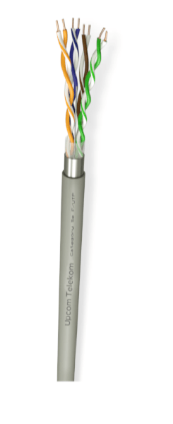
CAT 5e F/UTP Cable
CAT 5e F/UTP cable is designed for indoor structured cabling projects that require stable 100 MHz performance, an overall foil screen and dependable transmission for voice, data and Gigabit Ethernet. With 24 AWG bare copper conductors and PVC, HFFR or PE jacket options, it is a practical choice for commercial buildings, technical rooms and general LAN installations.
24 AWG Bare Copper
Overall Foil Shield
100 MHz Performance
10/100/1000Base-T
CAT 5e F/UTP Cable Overview
This shielded LAN cable is produced for balanced cabling systems that need reliable signal transmission together with an additional screening layer around the twisted pairs. The overall foil screen helps improve performance in routes where better protection against external interference is preferred, while the cable still keeps the practical handling expected from a Cat 5e solution.
Suitable for basic voice and data installations up to 100 MHz, this cable supports common Class D applications including Ethernet, Fast Ethernet and Gigabit Ethernet. It also fits naturally into broader fiber optic and data LAN cable projects where a shielded copper link is required within the structured cabling architecture.
Construction and Shielding Details
Conductor and pair structure
The cable uses 24 AWG bare copper conductors with PE insulation. This construction is widely preferred where stable electrical performance and consistent pair geometry are required for copper network links.
Screening and grounding support
A PES band, Al-Pet foil with 100% coverage and a tinned copper drain wire form the cable’s shielding package. This structure supports grounding continuity and adds an extra layer of screening for indoor network environments.
Outer sheath options
Depending on the project requirement, the outer sheath can be specified as PVC, HFFR or PE. This gives more flexibility when matching the cable to installation practice, building type and fire-performance expectations.
Construction summary
- 24 AWG bare copper conductor
- PE insulation
- PES band with full coverage
- Tinned copper drain wire
- Al-Pet foil with full coverage
- PVC, HFFR or PE outer sheath
CAT 5e F/UTP Technical Specifications
The values below help specifiers and procurement teams review mechanical, environmental and electrical suitability before final project approval.
Applications and Standards
Typical application areas
- IEEE 802.3 Ethernet networks
- 10Base-T, 100Base-T and 1000Base-T links
- IEEE 802.5 16 MB
- ISDN, TPDDI and ATM
- Power over Ethernet (PoE) and PoE+
- Indoor structured cabling for voice and data
Compliance references
- IEC 60754-2
- EIA/TIA-568-C.2
- ISO/IEC 11801 2nd edition
- IEC 61156-5
- EN 50173-1
- EN 50288-3-1
For broader reference on cabling governance, see TIA standards.
How to Select the Right Cable for a Project
A correct cable choice is not only about category. It should also match shielding level, installation route, jacket requirement and the expected network service.
-
Define the network service.
Confirm whether the channel will be used for voice, 10Base-T, 100Base-T or 1000Base-T and whether 100 MHz Cat 5e performance is sufficient for the project scope. -
Choose the right sheath.
Select PVC, HFFR or PE according to the building type, installation practice and project specification. -
Review routing conditions.
Check bend radius, available pathway and pulling conditions before installation to protect pair integrity. -
Verify environmental and mechanical limits.
Make sure the project stays within the stated installation temperature, operating temperature, tensile strength and crush resistance values. -
Compare with adjacent cable families.
If the project needs unshielded construction or a higher category, review the alternatives below before finalizing the bill of materials.
Compare Other LAN Cable Options
For category planning and nearby alternatives, use the links below. This keeps the page connected to the main category hub while helping users move naturally to adjacent cable types.
Fiber Optic and Data LAN Cables
Go to the main category page for the full copper and fiber cable range.
CAT 5e U/UTP Cable
A practical option for standard unshielded indoor network installations.
CAT 6 SF/UTP Cable
Step up to a higher category with additional screening for more demanding links.
CAT 7 S/FTP Cable
For projects that require higher performance and pair-level shielding.
CAT 7A S/FTP Cable
A higher-end shielded solution for advanced data cabling applications.
CAT 7A+ S/FTP Cable
Explore an upper-tier option when shielding and category requirements go beyond Cat 5e.
FAQ About CAT 5e F/UTP
What does F/UTP mean?
F/UTP indicates an overall foil shield around the twisted pairs, while the individual pairs remain unshielded.
Is this cable suitable for Gigabit Ethernet?
Yes. The cable is positioned for Class D applications and supports Ethernet, Fast Ethernet and Gigabit Ethernet use cases up to 100 MHz.
Which jacket options are available?
The outer sheath can be specified as PVC, HFFR or PE depending on the installation environment and project requirement.
What installation values should I review first?
Key values include a 50 mm minimum bending radius during draw-in, a 25 mm minimum bending radius after installation, maximum tensile strength of 100 N and operating temperature from -30°C to +70°C.
Can CAT 5e F/UTP be used for PoE and PoE+?
Yes. The application scope listed for this cable includes Power over Ethernet (PoE) and PoE+.
Need the full specification pack?
Download the datasheet for detailed values and continue to the main LAN cable category to review adjacent product families for your project.