10 Dec Fiber Blowing Best Practices
Fiber Blowing Best Practices
Efficient fiber blowing is not only about using a powerful machine or high-quality fiber. Field performance depends on engineering discipline: correct duct–cable pairing, airflow capacity, lubrication strategy, mechanical limits, and environmental planning.
This Fiber Blowing Best Practices guide gives installation teams a practical engineering checklist for FTTH, FTTB, OSP, and backbone deployments. For broader technical context, see our fiber optic cable blowing guide and how a cable blowing machine works.
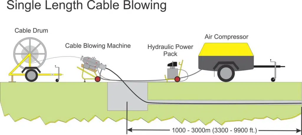
Start with route condition, cable OD, duct size, target length, and machine setup. If the wider project also includes cabling design and site planning, pair this page with our best fiber optic cabling installation practices guide. If you are comparing sourcing strategy on the supply side, our fiber optic importing guide for distributors can support procurement planning.
Why Engineering Quality Determines Fiber Blowing Success
In many failed installations, the main problem is not the fiber itself but technical misconfiguration: poor duct preparation, weak airflow planning, wrong lubrication, or ignoring bending and tensile limits.
Strong installation discipline increases blowing distance, reduces friction, helps prevent microbending, and protects the cable during installation. This is why Fiber Blowing Best Practices should be treated as installation engineering, not as a machine-only topic.
A more powerful machine does not correct a bad route. Clean duct condition, correct fit, stable air delivery, and controlled feeding decide whether the installation stays repeatable.
Cable & Duct Compatibility
This is the first decision point in any fiber blowing setup. Cable and duct sizing should never be decided only by nominal diameter; route condition, bend count, and airflow behavior matter as much as size.
- Cable-to-duct compatibility verified against manufacturer recommendations
- Duct inner surface checked: clean, dry, and free from debris
- No ovalization, crushing, or damage at the duct entry
- No tight bends in the first 3–5 meters of installation
- Duct diameter selected correctly for the cable outer diameter and route type
A “correct” nominal fit on paper can still fail in the field when the route has water, sharp bends, old duct surfaces, or poor sealing.
Air & Machine Setup
Compressor selection should be based on real delivered airflow at working pressure, not only on the pressure rating shown on a brochure. This is especially important on long routes or when hose size, fittings, and air temperature can reduce performance at the machine.
Machine-side checks
- Compressor delivered airflow and working pressure verified for the specific machine, cable, duct, and route length
- Machine rollers, belts, or drive wheels inspected for wear and correct pressure
- Jetting head aligned correctly with the duct entry
- Air pressure and sealing test completed before cable insertion
- Emergency stops and safety controls tested
Air-side checks
- Air filtration and moisture control checked before blowing starts
- Hose length and hose diameter considered as part of the compressor system
- Connections checked for leaks before the job starts
- Route-specific pressure behavior confirmed with a test section
- Hot or wet air managed before it reaches the blowing machine
Stable delivered airflow, correct sealing, clean duct condition, and controlled feeding usually matter more than simply increasing bar or psi.
Lubrication Strategy
For long-distance installations, the correct cable blowing lubricant can improve consistency and reduce avoidable friction. The goal is controlled application, not maximum quantity.
- Lubricant selected according to cable design and duct type
- Lubrication applied in a controlled and continuous way where needed
- Pre-lubrication considered for long routes, older ducts, or higher-friction applications
- Over-lubrication avoided, because excess lubricant can reduce control and cause cable oscillation
Universal Lubricant
General-purpose option for teams that need a broad-application lubricant reference in PDF format.
UP S LUB 20
Product page for a UPCOM cable blowing lubricant option suited to controlled field application.
UP-S-LUB-100XL
Alternative UPCOM lubricant page for teams comparing route length, cable type, and field condition.
Mechanical Limits & Environmental Conditions
Mechanical limits
- Maximum tensile rating checked in the cable manufacturer datasheet
- Crush rating reviewed against the expected route condition
- Minimum bend radius respected along the full route, including the entry zone and drum handling
- Installation speed kept within a controlled operating range
- Drum payoff arranged to avoid additional back tension
Environmental conditions
- Ambient temperature reviewed before blowing starts, because higher heat can increase friction and reduce stability
- Humidity or condensation inside the duct eliminated before installation
- Duct route checked for blockages, deformation, or water ingress
- Blowing avoided during rain when ducts or access points are not fully protected
Warm and wet compressed air can reduce consistency, especially on longer routes. For these situations, UPCOM’s Air Cooler can help stabilize the air supply before it reaches the blowing machine.
Pre-Start & Post-Blowing Checklist
Pre-start procedures
- Drum positioned to avoid back tension and side loading
- Drum brake adjusted for smooth rotation
- Field team communication established before startup
- Test blowing completed over the first section of the route
- Airflow, sealing, and pressure behavior monitored during the test phase
Post-blowing procedures
- Fiber end inspected for jacket condition and installation integrity
- Excess cable length managed according to the project requirement
- Route details documented for maintenance and future expansion
- Machine counters and field logs recorded after completion
- Site feedback captured for future route planning and machine setup
Common Mistakes in Fiber Blowing
Setup errors
- Starting the job with a wet or contaminated duct
- Choosing the cable and duct only by nominal size without checking route behavior
- Increasing pressure without solving airflow loss, sealing problems, or duct friction
Control errors
- Using the wrong lubricant or applying too much lubricant in one point
- Ignoring cable bend radius and tensile limits during entry and payoff
- Treating machine power as a substitute for route preparation
Many field problems that look like machine issues are actually setup issues. For buyers planning complete cable packages or distributor sourcing strategy, our fiber optic importing guide for distributors can help on the procurement side as well.
Why Engineering Parameters Matter More Than Cable Price
Lower cable price alone rarely improves project performance. Better engineering control usually delivers more value through longer blowing distance, lower installation time, lower rework risk, and more consistent network quality.
- Longer and more stable blowing distance
- Lower installation time and fewer restarts
- Reduced risk of cable damage
- Better long-term network reliability
Smart engineering beats cheap materials. Every time.
Frequently Asked Questions About Fiber Blowing Best Practices
What causes most fiber blowing failures in the field?
Most failures come from setup errors rather than the cable itself: dirty or wet ducts, poor cable-duct matching, insufficient delivered airflow, wrong lubrication, or ignored bend and tensile limits.
Is higher pressure always the answer in fiber blowing?
No. Stable delivered airflow, correct sealing, duct condition, and controlled feeding are just as important. Raising pressure without fixing the real restriction usually does not improve the route outcome.
When should an air cooler be used in cable blowing?
An air cooler becomes useful on long routes, in warm conditions, and anywhere hot or wet compressed air can reduce installation consistency.
Should lubricant be used on every job?
Not automatically. Lubricant choice and quantity depend on the cable design, duct condition, route length, and the overall installation setup. Use only compatible products and apply them in a controlled way.
External References
| Source | Why it is relevant |
|---|---|
| The FOA Reference for Fiber Optics – Fiber Optic Installation | Practical installation background for handling, route discipline, and field-side precautions. |
| Corning – Air-Assisted Cable Installation Techniques | Useful external engineering context for air-assisted installation methods and cable handling logic. |
| Dura-Line – MicroDuct & Cable Selector / Fill Ratio Tool | Supports duct and cable selection logic when teams want a fit-checking reference. |
Need the right machine and installation setup for the same project?
Send UPCOM the cable OD, duct size, target length, and route condition. That makes it easier to recommend the correct machine, accessories, and airflow-side package together rather than treating each item separately.