
Cable Spooling Machines: Selection and Setup Guide
Cable spooling machines transfer cable onto a receiving reel with controlled rotation and a suitable winding pattern. A useful specification starts with the cable's handling limits, the reel dimensions and the required cut length—not an advertised maximum speed alone.
This guide explains payoff, take-up, tension control and acceptance checks. It also shows where UPCOM's drum roller belongs in a cable-handling setup.
How cable spooling machines work
A basic respooling line has a supply reel, a controlled cable path and a receiving reel. The supply side is the payoff; the receiving side is the take-up. Between them, guides, a measuring device and a traverse mechanism can manage the cable path and build orderly layers.
The functions should be specified separately. A motor rotates a reel; it does not automatically measure tension. A counter measures passing cable; it does not guarantee an accurate cut if the measuring wheel slips. A traverse distributes the cable across the receiving reel; its settings must match the reel width and cable diameter.
Distinguish respooling from field installation. A cable blowing machine feeds a cable into a duct with air assistance; it is not a substitute for a take-up system. The cable blowing machine working-principle guide explains that equipment's role.
Compare cable spooling machines by control level
| Equipment type | Typical task | What to verify |
|---|---|---|
| Manual winding setup | Occasional transfers and short lengths | Handling effort, reel restraint, cable guidance and repeatability |
| Motorized / operator-assisted | Regular cutting and respooling | Speed control, braking, traverse arrangement, measurement and stop response |
| Automated respooling line | Repeated lengths or integrated production | Feedback, recipes, coordinated drives, measured-length stopping and fault handling |
| Passive reel support | Supporting reel rotation during payoff | Reel dimensions, support rating and suitability for the planned operation |
Higher automation can reduce repeated operator adjustments, but its value depends on the mix of cables and orders. A workshop processing many short batches may spend more time loading reels and changing settings than winding. Measure that complete cycle before comparing alternatives.
Do not treat these equipment classes as a claim that UPCOM supplies every configuration. The verified UPCOM accessory discussed below is the cable drum roller. Any powered spooler proposal needs a model-specific datasheet and an agreed scope of supply.
Size the cable, receiving reel and support together
Start with the exact cable part number. Record its outer diameter, mass per metre, permitted tension and minimum bend radius under the relevant operating conditions. Different fiber, copper and armored constructions can require different settings even when their diameters match.
Flange diameter is not the winding diameter
The flange is the outer side plate of the reel. The barrel is the surface supporting the first cable layer. A large flange does not prove that the barrel satisfies the cable's bending limit. If the required bend radius is R, the corresponding bend diameter is 2R; compare that diameter with the barrel and every guide surface in the cable path.
Also check the usable distance between flanges, arbor-hole diameter, shaft or pintle compatibility, flange condition and required free space above the wound cable. A reel that physically fits a machine may still have too little usable volume for the ordered length.
Loaded mass example: 1,000 m of cable at 0.12 kg/m contributes 120 kg. Add an 80 kg empty reel and the static total is 200 kg. Support capacity, lifting arrangements and drive suitability must cover the actual loaded configuration. This calculation is an example, not a rating for the UPCOM drum roller.
Reel capacity estimates are useful for planning, but packing changes with cable shape and winding quality. Confirm usable capacity through the reel supplier's data or a representative winding trial. Review the cable product families and the fiber cable handling guide when defining cable limits.
Cable spooling machines: speed, torque and tension
The winding radius increases as the take-up reel fills. At a fixed rotational speed, cable line speed therefore rises. To maintain constant line speed, the reel must turn more slowly as its wound diameter increases.
Basic relationships:
Line speed v = 2πrn
Steady cable torque T ≈ F × r
Here r is the effective winding radius, n is revolutions per minute when v is in metres per minute, and F is cable tension in newtons. Torque is in newton-metres. Actual drive sizing also includes acceleration, friction and system losses.
Calculated example: at 60 m/min, a 0.20 m winding radius needs about 47.7 rpm; a 0.40 m radius needs about 23.9 rpm. Holding 100 N of cable tension would require approximately 20 and 40 N·m of steady cable torque respectively. These figures illustrate the relationship; they are not machine settings or permissible cable loads.
Ask how tension is controlled through starting, normal winding, slowing and stopping. Options may include a coordinated drive system, load-cell feedback, a dancer arrangement or a controlled brake. The supplier should explain the operating range and how it handles changing reel diameter and inertia.
A speed control knob and an emergency stop do not establish tension accuracy. If tension is a purchase criterion, specify where it is measured, the required range, allowable variation and the response to a fault. For a fiber cable, acceptance should cover transient peaks as well as average tension.
Check layer quality and measured-length accuracy
Traverse settings
The traverse moves the entry point across the reel. For a regular round cable, pitch relates to its diameter and the desired laying pattern. Too little travel or a poorly timed reversal can pile cable against a flange; poor pitch can leave gaps or crossovers. Use a trial to validate the settings for the actual cable and reel combination.
Length measurement
A measuring wheel needs suitable contact, alignment and calibration. Surface contamination, wheel wear and slippage can change the result. Compare several representative cut lengths with an independent reference and state the allowed error in the purchase specification.
Define whether the quoted length includes test tails or termination allowances. Record the starting and ending metre marks where the jacket provides them, but do not assume that printed marks replace the agreed measurement method. Repeated short orders and one long order may need different acceptance checks.
Winding quality and optical performance should both be checked for fiber cable. A neat outer layer does not reveal every inner crossover or damaged section. The fiber optic loss guide explains how handling defects can affect the finished link.
Set up and check a respooling operation
Use the equipment manual and the selected cable manufacturer's procedure for the operation. The checks below are a planning framework; the approved settings and protective measures belong to the specific machine and cable.
- Verify the job: cable part number, required length, receiving reel and available cable balance.
- Inspect the reels and route: reject damaging edges, loose hardware or obstructions; align the path through the guides and measuring device.
- Confirm limits: barrel and guide diameters, loaded reel mass, cable tension and the approved winding speed.
- Set the controls: establish traverse limits, counter reference and coordinated start/stop behavior before a production run.
- Run a short trial: observe the first layers, measured length and tension behavior. Stop the equipment before correcting the winding or cable path.
- Finish and identify the reel: secure and protect cable ends using the cable supplier's method; label the part number, length and traceability information.
For optical cable, Corning's cutting and respooling procedure (PDF) explains reel selection, traverse and cable-handling concerns. Apply its cable-specific instructions only to the products it covers.
During payoff, uncontrolled reel overrun can loosen layers and introduce tangles. Store and restrain reels appropriately and inspect them before use. Corning's reel-handling note (PDF) discusses these failure modes and storage practices. A cable's maximum pulling load should not be treated as a routine winding target.
Where UPCOM cable-handling accessories fit
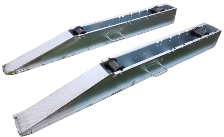
The UPCOM Cable Drum Roller supports drum rotation during payoff and handling. Its datasheet states a drum-diameter range of 300–1350 mm and an adjustable rear roller position for different drums.
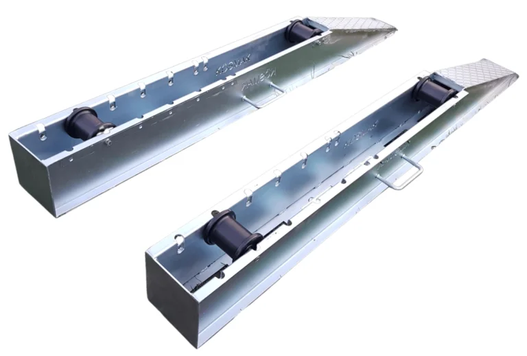
This published diameter range is not a motorized winding-speed, tension-control or load-capacity rating. The drum roller has no take-up drive, counter or automatic traverse. Confirm the permissible loaded mass and the proposed use before including it in a respooling line.
Download the Cable Drum Roller datasheet (PDF).
For field work, the cable fleeting trailer addresses a different cable-handling task between installation stages. The cable blowing machine range covers duct installation. Select the support equipment around the actual workflow using the installation equipment guide and the fiber jetting guide.
Cable spooling machines: RFQ and acceptance checklist
A comparable quotation should state what is supplied and demonstrate performance with the intended cable and reels. Include these items rather than asking only for an “automatic cable winder.”
- Cable envelope: constructions, diameter and mass range, tension limits and required bend radii.
- Reel envelope: flange and barrel diameters, usable width, arbor dimensions, empty and loaded mass.
- Process requirement: cut lengths, batch sizes, loading frequency and required line speed under representative conditions.
- Control requirement: tension feedback or braking method, traverse adjustment, counter accuracy and fault response.
- Installation requirement: floor space, power supply, reel-loading method and operator access.
- Scope of supply: payoff, take-up, counter, guides, cutter if required, guarding, commissioning, training and documentation.
- Support requirement: consumables, spare parts, maintenance access, service arrangements and delivery terms.
Agree the test before placing the order
Use representative cable and reels. Check several cut lengths, first and final layers, tension variation and coordinated stopping. Document results and the accepted operating window. If a supplier claims faster output, compare complete cycle time—including loading and changeover—against your existing process.
For fiber cable, agree the optical test method and acceptance limits before and after the trial. Mechanical inspection and optical measurements answer different questions. Visible cable damage still needs assessment even if an optical test passes.
Plan the cable-handling part of your installation
Use the UPCOM product pages to request a quote for documented accessories. Send drum dimensions, loaded mass, cable type and the intended handling task.
Cable spooling machines: frequently asked questions
Is a cable drum roller a cable spooling machine?
No. A passive drum roller supports reel rotation. A powered take-up system winds the receiving reel; measuring, tension control and traverse functions must be specified separately.
Can the same machine respool fiber optic and power cables?
Possibly, if its reel, drive, guide and control ranges cover both cables. Verify each cable's tension, bending and crushing limits and validate the setup with representative trials.
Why does take-up rpm change as the reel fills?
The effective winding radius increases with each layer. Maintaining constant cable line speed requires lower reel rpm; steady torque for the same cable tension increases with radius.
Does an automatic spooler guarantee accurate cut lengths?
No. Accuracy depends on the measuring system, calibration, cable contact, slippage and stopping behavior. Specify an allowable error and verify it over representative cut lengths.
What information should I send for a drum roller quotation?
Send the cable type, drum flange diameter, width, loaded mass and intended operation. The published UPCOM diameter range is 300–1350 mm; confirm the remaining compatibility requirements for the proposed setup.