
Cable Blowing Machine Selection Guide: Cable OD, Duct & Distance
Cable blowing machine selection should start with the actual cable outside diameter, then move to duct OD/ID, route length, bends, drive preference and available compressor capacity. Choosing by “largest machine” or maximum distance alone usually creates unnecessary cost or the wrong tooling package.
This guide compares UPCOM platforms from compact FTTH machines to pneumatic and hydraulic backbone systems, and shows which project data should drive the final configuration.
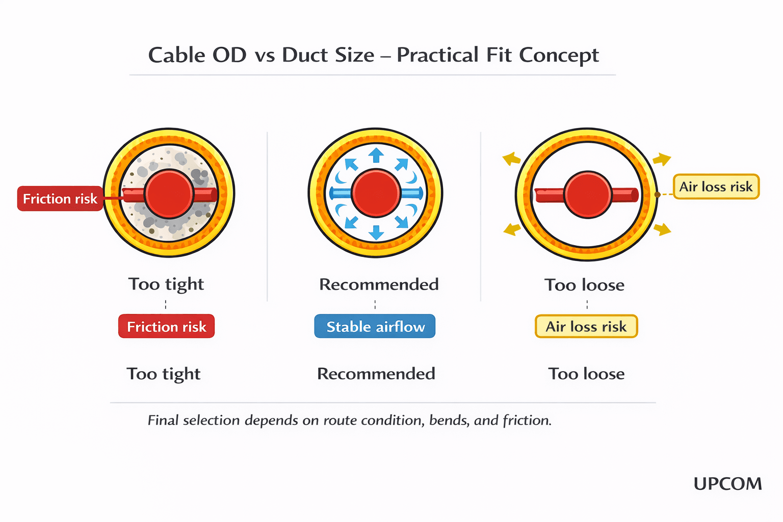 Start with measured cable OD and duct ID/OD. Distance and drive type come after physical compatibility.
5-Step Cable Blowing Machine Selection Workflow
A machine can be physically compatible with the cable and still be a poor project fit. Use the sequence below before comparing price, package content or maximum speed.
Measure the cable outer diameter
Use the actual cable OD from the datasheet or measured cable. Pallets, rollers, cable guides and seals are selected around this number. This is the fastest way to eliminate machine families that do not physically match the project.
Confirm duct OD and duct ID
Duct OD is used to select the connection tool and mechanical interface. Duct ID determines cable clearance, available annular air space and cable-to-duct fill ratio. Do not use one as a substitute for the other.
Define route length and geometry
Record the target section length, bend count, approximate bend radii, couplers, elevation change and duct condition. A 700 m straight route and a 700 m route with repeated bends are not equivalent machine-selection cases.
Choose the drive architecture that fits the site
Compact drill-powered, electric, pneumatic and hydraulic machines solve different logistics problems. Site access, portability, available utilities, operator preference and required feed force all matter.
Validate compressor and tooling before ordering
Final selection is the complete operating system: machine + cable tooling + duct connection + sealing + compressor + lubrication/support equipment where required. A correct machine with the wrong setup will still perform badly.
Cable Blowing Machine Selection: Quick Selector
The table uses the current technical ranges published on UPCOM product pages. Maximum distance figures are reference capabilities under suitable conditions; use the Cable Blowing Distance & Performance Guide for realistic field-planning logic.
| Machine | Cable range | Duct range / tooling | Drive | Published distance reference | Typical project fit |
|---|---|---|---|---|---|
| MikroFOK | Ø1–6 mm | Ø7–20 mm duct OD | Pneumatic | No fixed maximum stated | FTTH, microcable and compact pneumatic work |
| DrillFOK | Ø1–8 mm | Project-specific duct tooling | External cordless drill + compressed air | Up to 1,000 m* | Portable service work, last-mile, indoor and short/medium microduct routes |
| ElektroFOK | Ø1–8 mm | Ø4–18 mm | Electric | Up to 1,000 m* | Microcable projects needing electric speed/torque control |
| MiniFOK | Ø2.5–12 mm | Connection options Ø7 / 10 / 12 / 16 / 20 / 32 / 50 mm | Pneumatic | Up to 1,500 m* | Mixed FTTH, feeder and access-network work requiring a wider compact range |
| MiniFOK Genius | Ø4–8 mm | 14 / 16 mm tooling listed in current compatibility data | Public drive type not stated | Validated public distance not stated | Dedicated 4–8 mm configurations where the Genius monitoring platform is specified |
| FOK | Ø9–22 mm | Ø20–50 mm duct OD | Dual pneumatic | Up to 3,000 m at Ø12 mm cable / Ø40 mm duct* | Backbone, metro, feeder and recurring telecom contractor work |
| HidroFOK | Ø9–24 mm | Ø20–60 mm duct OD | Hydraulic | Up to 3,000 m at Ø12 mm cable / Ø40 mm duct* | Heavy-duty, larger cable and more demanding long-route installations |
* Published reference figures depend on cable construction, duct quality, route geometry, sealing, lubrication, compressor output and operator setup. They are not guaranteed site results.
When to Choose Each UPCOM Cable Blowing Machine
Use when the project is concentrated in the Ø1–6 mm range and a compact pneumatic microcable platform is preferred.
View MikroFOK →Use when transport weight, fast mobilization and the ability to power the feed mechanism with a cordless drill are important.
View DrillFOK →Use when Ø1–8 mm cable projects benefit from an integrated electric drive, touchscreen monitoring and remote-control functions.
View ElektroFOK →Use for mixed Ø2.5–12 mm work where the crew needs a pneumatic machine that bridges microcable and smaller feeder applications.
View MiniFOK →Use for Ø9–22 mm telecom cables when a pneumatic backbone machine with broad duct compatibility is the appropriate platform.
View FOK →Use for larger cable ranges, higher feed-force requirements and routes where a hydraulic platform is justified by field conditions.
View HidroFOK →For the two most common overlap decisions, see MikroFOK vs ElektroFOK and FOK vs HidroFOK.
Duct OD, Duct ID and Fill Ratio
Two duct dimensions serve different purposes:
- Duct OD identifies the connection tool, insert and mechanical interface.
- Duct ID determines the space available for the cable and the airflow around it.
- Fill ratio for air-assisted installation is calculated from cable OD ÷ duct ID × 100.
For microduct applications, Corning's air-assisted installation guidance recommends a 50–80% fill-ratio range for the applications covered by its guidance. That is an engineering reference, not a universal machine-selection rule.
Use Distance as a Project Check, Not the First Filter
A target distance matters only after the cable and duct combination is physically compatible. Published distance values are best-case reference capabilities; actual single-run performance changes with cable weight and stiffness, duct cleanliness, bend count, elevation, lubrication, sealing quality and compressor airflow.
Straight, clean route
Usually gives the highest chance of approaching published performance because route resistance stays low.
Multiple bends or couplers
Reduces achievable distance and makes duct proofing, sealing and lubrication more important.
Long route with uncertain duct
Plan intermediate access or cable fleeting instead of assuming one-shot installation from the headline machine figure.
Use the distance and field performance guide for typical single-run ranges and 8-hour planning output.
Pneumatic, Electric, Drill-Powered or Hydraulic?
Pneumatic drive
MikroFOK, MiniFOK and FOK use pneumatic drive architectures. They suit crews that already work with compressed-air systems and want machine families spanning microcable to backbone applications.
Electric drive
ElektroFOK is designed for Ø1–8 mm microcables with integrated electric control, making it useful where consistent speed/torque control and monitoring are preferred.
Drill-powered feed
DrillFOK uses an external cordless drill for feed force while compressed air supports the installation. Its main advantage is portability and simple field logistics.
Hydraulic drive
HidroFOK uses a hydraulic power unit with dual hydraulic motors. It is the heavy-duty choice when larger cable sizes and higher feed-force requirements justify the additional equipment.
Machine Selection Is Only Half the Configuration
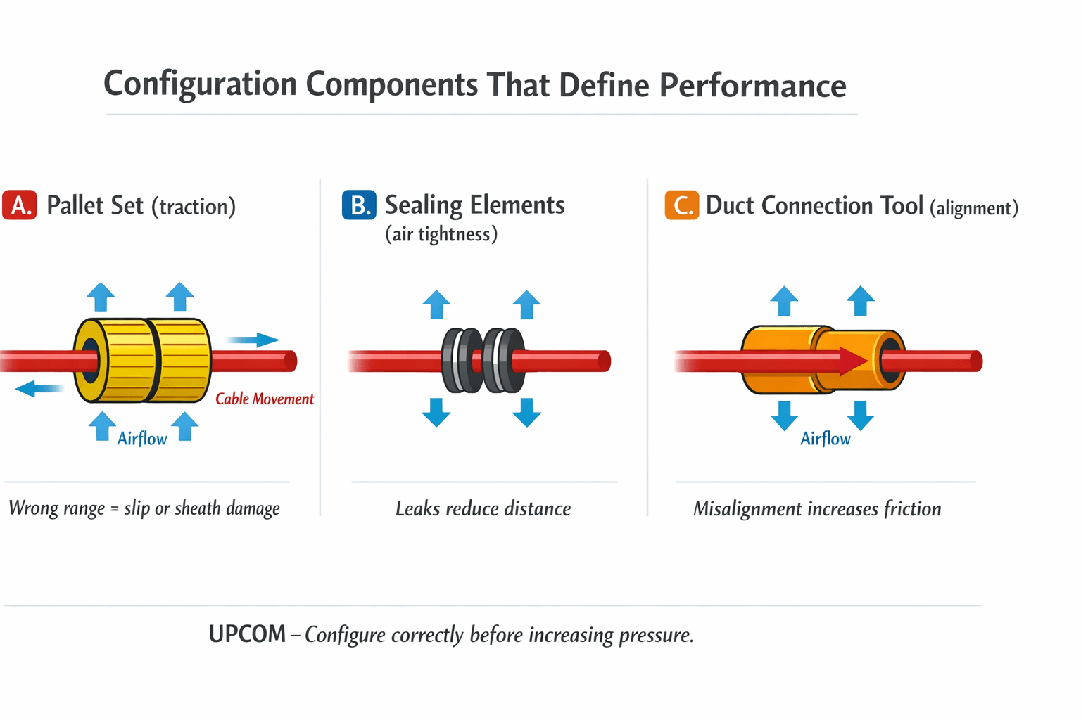
- Match pallet or roller range to the actual cable OD.
- Match cable guides, nutrings and seals to the cable range.
- Match the duct connection tool to duct OD.
- Check duct ID for clearance and airflow.
- Confirm compressor delivery at the required working pressure.
- Add air cooling, cable handling or lubricant support where the project requires it.
For machine-specific component matching, use the Cable Blowing Machine Spare Parts & Compatibility Guide.
Compressor check
Pressure alone is not enough. Large ducts and long routes may need substantially more delivered air volume than compact microduct jobs. Before finalizing a machine, check the air compressor selection guide. For hot discharge air or moisture-management concerns, review the Air Cooler.
Common Cable Blowing Machine Selection Mistakes
Choosing only by maximum distance
A machine's distance benchmark does not override cable and duct compatibility or route geometry.
Using duct OD as fill-ratio data
OD selects the connection tooling. ID is the dimension that belongs in cable-to-duct clearance calculations.
Buying the largest machine “for flexibility”
Oversizing can add purchase, transport and setup cost without improving a small-cable project.
Ignoring compressor delivery
A compressor can show the required pressure and still lack the airflow needed for the duct volume and route.
Quoting before checking tooling
Machine price alone is incomplete if the required pallet, roller, seal and duct-tool groups have not been matched.
Treating the route as a straight line
Bends, couplers, elevation and duct condition create the real resistance profile that determines field performance.
What to Send for an Accurate Machine Recommendation
- Cable OD (mm) and cable construction/type
- Duct OD (mm)
- Duct ID (mm)
- Target section length
- Approximate bends, couplers and elevation changes
- Available compressor pressure and air delivery
- Indoor/outdoor and site-access limitations
Why this reduces quotation errors
With those inputs, machine family and tooling can be checked together. That reduces follow-up questions, prevents unnecessary accessory combinations and makes freight/package planning more accurate.
If you already have these values, use the Cable Blowing Machine Quote form.
Technical References
The sources below support the general installation principles used in this guide. UPCOM model capacities and configuration data should be taken from the relevant product page and datasheet.
| Reference | Relevant selection principle |
|---|---|
| Corning — Microduct Cable Air-Assisted Installation Considerations | Fill ratio, duct proofing, cable handling, compressor/cooling and route-condition considerations. |
| FOA — Fiber Optic Cable Plant Installation Standard | Duct cleaning/sealing, cable size/weight, air flow, friction and route factors affecting blowing distance. |
FAQ: Cable Blowing Machine Selection
What is the first parameter for selecting a cable blowing machine?
Start with the actual cable outside diameter. It determines which machine families and cable-gripping components are physically compatible. Then validate duct OD/ID, route and compressor requirements.
Should I select the machine mainly by maximum blowing distance?
No. Maximum distance is a reference capability, not the first selection filter. Cable OD, duct size, route geometry, tooling and compressor capacity must be compatible first.
Why do you need both duct OD and duct ID?
Duct OD is used for connection-tool selection. Duct ID controls cable clearance, fill ratio and the air space available around the cable.
When should I choose FOK instead of HidroFOK?
FOK is a pneumatic Ø9–22 mm platform for standard backbone and feeder work. HidroFOK extends the cable and duct range and uses hydraulic drive for projects where heavier-duty feed capability is justified.
When should I choose MikroFOK, DrillFOK or ElektroFOK?
All serve small-cable applications but use different drive concepts. MikroFOK is compact pneumatic, DrillFOK is drill-powered and ElektroFOK uses an integrated electric drive. Site logistics and control preferences help separate them after cable/duct compatibility is confirmed.
What information is needed for a project-specific quotation?
Send cable OD, duct OD, duct ID, target length, route notes including bends/elevation, and available compressor pressure/air delivery. This is enough to start matching the machine and tooling package.
Need the Machine and Tooling Matched to a Real Project?
Send the measured cable OD, duct OD/ID, route length and compressor data. UPCOM can check the machine family, cable tooling, duct connection and supporting equipment as one configuration.