
Cable Blowing Distance & Field Performance Guide
Cable blowing distance is not a fixed number printed on a machine label. Real distance depends on cable construction, duct internal diameter, fill ratio, bends, lubrication, sealing quality, route condition and the compressor's delivered airflow.
This guide separates published machine capability from typical field planning ranges, so contractors can compare UPCOM machines without treating best-case specifications as guaranteed site performance.
 FOK · 9–22 mm
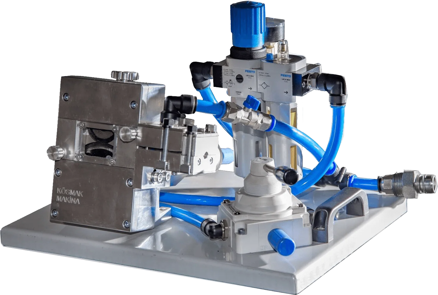 MikroFOK · 1–6 mm
Maximum vs Typical Cable Blowing Distance
A published maximum is a machine capability measured under a suitable cable, duct and route combination. A typical single run is a more conservative planning range for real field work. Those numbers answer different questions and should not be presented as interchangeable.
Published maximum
Useful for understanding the upper capability of a machine under a defined reference setup. It does not mean every cable and duct route will reproduce the same result.
Typical single run
Better for early project planning because it allows for route bends, duct condition, normal setup variation, cable stiffness and real compressor performance.
For example, FOK and HidroFOK publish up to 3,000 m at the reference combination of Ø12 mm cable and Ø40 mm duct. The field-planning ranges below are intentionally lower because route conditions are rarely identical to a reference setup.
UPCOM Cable Blowing Distance & Performance Comparison
The table combines published machine figures with conservative field-planning ranges. The “typical” columns are engineering references for estimating a project; they are not contractual guarantees.
| Model | Official cable / duct range | Published maximum | Typical field speed | Typical single run | Indicative 8-hour blowing output |
|---|---|---|---|---|---|
| HidroFOK | Ø9–24 mm cable / Ø20–60 mm duct OD | 80 m/min / up to 3,000 m* | 35–60 m/min | 1,000–2,000 m | 4–8 km |
| FOK | Ø9–22 mm cable / Ø20–50 mm duct OD | 80 m/min / up to 3,000 m* | 35–55 m/min | 800–1,500 m | 3–6 km |
| MiniFOK | Ø2.5–12 mm cable / Ø7–40 mm duct tooling | 80 m/min / up to 1,500 m | 30–50 m/min | 500–1,200 m | 2.5–5 km |
| MiniFOK Genius | Ø4–8 mm cable / 14–16 mm duct tooling | Validated field range not published | Not published | Not published | Not published |
| MikroFOK | Ø1–6 mm cable / Ø6–20 mm duct OD | 80 m/min / fixed maximum distance not stated | 25–50 m/min | 300–800 m | 2–4 km |
| DrillFOK | Ø1–8 mm cable | 90 m/min / up to 1,000 m | 20–40 m/min | 200–600 m | 1.5–3 km |
| ElektroFOK | Ø1–8 mm cable / Ø4–18 mm duct | 90 m/min / up to 1,000 m | 25–50 m/min | 300–800 m | 2–4 km |
* FOK and HidroFOK 3,000 m figures use the published Ø12 mm cable / Ø40 mm duct reference. Typical speed, single-run distance and shift output are engineering planning ranges and vary with cable, duct, route, airflow, temperature and operator setup.
Cable-to-Duct Ratio and Cable Blowing Distance
For performance calculations, use the duct internal diameter (ID). Machine connection tooling is often selected by duct outside diameter, but the annular air space that carries the cable is governed by the duct ID.
Example: a 6 mm cable inside a 10 mm duct ID gives a 60% ratio.
For microcable and microduct work, a roughly 50–75% range can be used as a general engineering reference. Corning's air-assisted installation guidance cites a 50–80% recommended fill-ratio range for the microcable applications covered by that document. Project-specific cable and duct guidance still takes priority.
Why the ratio changes performance
- Too tight: less free air space and higher sensitivity to cable/duct friction.
- Too loose: more air volume is required and mechanical pushing effectiveness may change.
- Bends matter: a ratio that works on a straight route may behave differently on a route with repeated bends.
- Duct ID, not OD: using OD in a fill-ratio calculation gives the wrong engineering picture.
Compressor Airflow and Cable Blowing Distance
Pressure and airflow are different parameters. A compressor that can reach 12 or 15 bar is not automatically suitable for a job if it cannot maintain the volume of air required by the duct ID, hose system, leakage and route length.
Pressure
Creates the driving air condition inside the duct. It must stay within the limits of the blowing machine, duct system, couplers and cable installation procedure.
Air volume
Becomes increasingly important as duct ID grows. Larger ducts can consume substantially more air even when the pressure target looks similar.
Air treatment
Hot or wet compressed air can reduce installation consistency. Air cooling and moisture management become more relevant on long routes and in warm conditions.
For project-side compressor sizing, use the air compressor selection guide. Where compressor discharge temperature or moisture is a concern, review the UPCOM Air Cooler.
Typical Cable Blowing Speed
Maximum machine speed is a mechanical capability. Actual operating speed is normally lower because the operator has to respond to cable stiffness, bends, duct condition, airflow stability and changing route resistance.
A slower, stable installation can produce a better overall result than starting at the machine's maximum speed and repeatedly stopping to solve grip, heat or route problems.
Indicative Output per 8-Hour Shift
The shift-output figures in the comparison table represent potential cable blowing output across multiple prepared duct sections.
They exclude civil works, duct repair, drum logistics, route access delays, major cleaning work and unusual site restrictions. Use them to estimate a productive blowing shift, not the total duration of a construction package.
What Reduces Cable Blowing Distance in the Field?
When cable stops earlier than expected, machine power is only one possible cause. The following factors usually deserve attention first.
How to Improve Cable Blowing Distance
- Proof, clean and dry the duct before the installation starts.
- Confirm actual cable OD and actual duct ID instead of relying only on nominal labels.
- Match rollers, pallets, seals and duct holders to the real project dimensions.
- Check delivered compressor airflow at working pressure, not only the compressor's headline bar rating.
- Use a compatible cable blowing lubricant in a controlled quantity when the route and duct type justify it.
- Keep drum payoff aligned and low-friction so the machine is not fighting reel resistance.
- Increase feed speed and air gradually, then record settings that work for repeat sections.
Use a route-based workflow
For the full operating sequence — duct preparation, machine setup, air calibration, troubleshooting and safety — use the Fiber Optic Cable Blowing Guide.
For field-side setup discipline, see Fiber Blowing Best Practices. For friction reduction, review the UP-S-LUB-100XL cable blowing lubricant.
Choose a Cable Blowing Machine by Distance and Cable Diameter
Distance target alone should not select the machine. Start with cable OD and duct dimensions, then use route difficulty and expected single-run distance to choose the platform.
Micro & FTTH work
For very small cables and microduct routes, compare MikroFOK, DrillFOK and ElektroFOK.
Mixed mid-range projects
MiniFOK covers a broader compact range where installers need more cable capacity without moving directly to the large-machine class.
For a diameter-first comparison of all machines, see the UPCOM cable blowing machine range and the dedicated selection guide.
Technical References for Cable Blowing Performance
External references are useful for checking the engineering principles behind fill ratio, airflow, route preparation and air-assisted installation. Machine-specific limits should still be taken from the relevant machine and cable documentation.
| Reference | Why it is useful |
|---|---|
| Corning — Microduct Cable Air-Assisted Installation Considerations | Field guidance on fill ratio, duct preparation, air cooling and realistic microcable jetting considerations. |
| Dura-Line — Choosing the Right Air Compressor | Explains why compressor pressure, delivered air volume and air treatment must be considered together. |
| FOA — Fiber Optic Cable Plant Installation Standard | Independent installation guidance covering duct preparation and the main variables that affect blowing distance. |
FAQ About Cable Blowing Distance
How far can fiber optic cable be blown in one run?
There is no universal single-run distance. Depending on cable, duct, route and equipment, projects may range from a few hundred metres to well above one kilometre. Some UPCOM machines publish maximum reference distances up to 3,000 m under defined conditions.
Why is the typical cable blowing distance lower than the published maximum?
Published maximums are reference capabilities under suitable conditions. Real routes include bends, variable duct condition, compressor losses, cable stiffness, access constraints and setup differences, so a conservative planning range is more useful for project execution.
Does higher pressure always increase cable blowing distance?
No. Pressure without adequate air volume, sealing and a clear route may not improve performance. Excessive pressure can also exceed the limits of the duct, couplers, cable or machine. Follow the applicable equipment limits and size the compressor for delivered airflow as well as pressure.
What cable-to-duct ratio should be used for microcable blowing?
A roughly 50–75% cable-OD-to-duct-ID ratio is a useful general engineering reference for many microduct applications. Corning guidance for the microcable applications covered by AEN096 cites 50–80%. The cable and duct manufacturer's project-specific guidance should take priority.
Which UPCOM machine is best for long-distance cable blowing?
Machine choice depends first on cable and duct size. For larger telecom cables and long routes, FOK and HidroFOK are the main UPCOM platforms. For smaller cables, a compact machine may be the better fit even when the route is long.
Need a Route-Based Machine Recommendation?
Send the cable OD, duct OD and ID, target route length, approximate bend count and available compressor capacity. UPCOM can match the machine and tooling configuration to the actual project instead of sizing from distance alone.