
Emerging Trends in Fiber Optic Technology: What Changes Network Design?
Emerging trends in fiber optic technology matter when they change a link budget, a duct plan or the cost of an upgrade. A faster laboratory result does not automatically produce a cable that a contractor can install on an existing route. For network owners, the useful question is which developments can be specified now, and which still need a qualified pilot.
Which fiber technology trends are ready for deployment?
The market contains several different kinds of progress: better use of existing single-mode fiber, denser conventional cable designs, and changes to the optical waveguide itself. They have different purchasing and operational consequences. Treating them as one upgrade path hides the work needed at the interfaces.
| Development | Where it fits | Decision before purchase |
|---|---|---|
| Higher-density cables and connectivity | Constrained ducts, equipment rooms and expanding access networks | Check cable mechanics, usable tray capacity, connector access and cleaning. |
| Coherent transmission and wavelength expansion | Capacity upgrades on qualified single-mode routes | Qualify the optical path and the complete active line system. |
| XGS-PON migration | Higher-capacity access services on a compatible optical distribution network | Check OLT/ONT support, coexistence filtering and loss budget. |
| Hollow-core fiber | Selected low-latency and cloud-network deployments | Require an approved cable, jointing method and installation plan. |
| Multicore transmission | Research and project-specific development | Qualify fan-in/fan-out interfaces, splicing and the transmission system. |
These categories describe different levels of engineering readiness. A commercially available component can still be unsuitable for a particular installed network.
Higher density changes cable handling and connection management
Reducing cable diameter can free duct space and make additional fiber counts possible on an existing route. The practical gain depends on the entire cable construction: jacket friction, stiffness, tensile rating, crush performance and the duct condition. A smaller cable is not automatically easier to install.
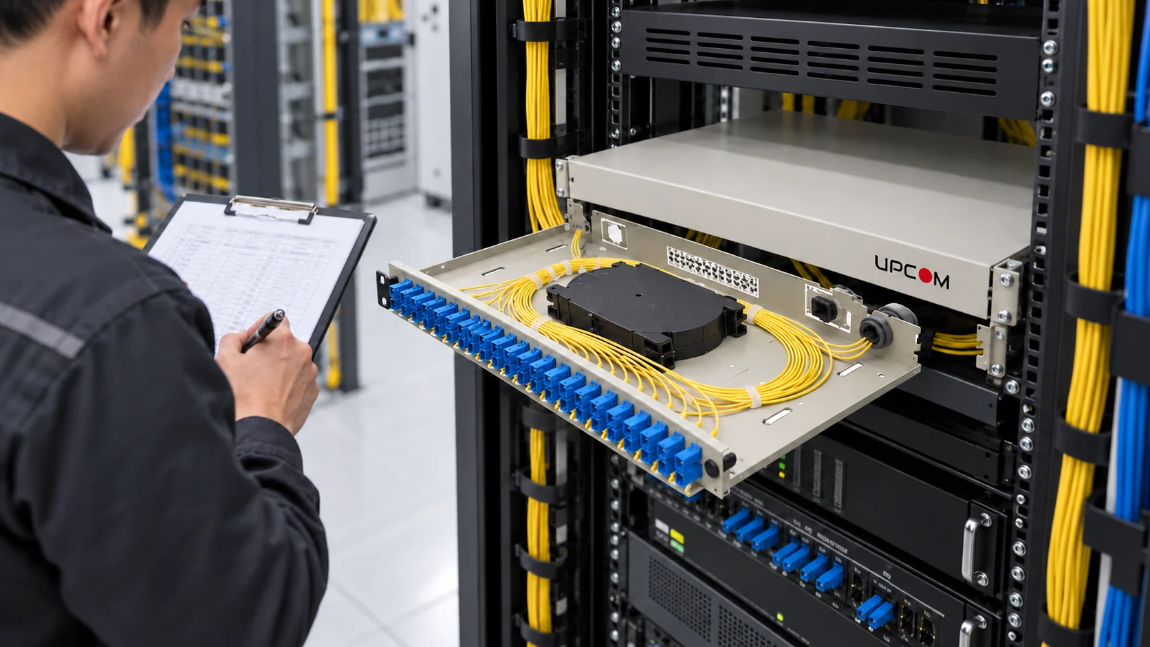
Inside the rack, increasing port density moves the constraint toward access. Technicians still need room to inspect connector endfaces, remove one patch lead without disturbing adjacent circuits and store slack without tight bends. A panel that fits the nominal fiber count can be difficult to maintain once fully populated.
Start with the route and service plan when comparing fiber optic cable constructions. Match the termination layout to patch-panel capacity and routing, and use the MPO polarity and loss-budget guide when a parallel optical interface requires multifiber connectivity.
Specify usable capacity: installed fibers, spare positions, accessible splice storage and room for the next maintenance intervention. Nominal port count alone does not measure it.
Capacity upgrades can come from the transmission system
Operators can increase capacity by changing modulation, using additional wavelengths or upgrading terminal equipment on a suitable existing fiber route. This is different from replacing a conventional single-core fiber with a multicore fiber. The first approach may reuse the passive plant; the second changes the transmission medium and its interfaces.
A route survey should establish fiber type, end-to-end attenuation, splice and connector events, and the impairments relevant to the intended system. For an extended wavelength range, qualify performance across that range rather than extrapolating from a single test wavelength. Amplifiers, filters and monitoring equipment must support the proposed design.
The procurement question is therefore specific: can this cable plant support the selected optical system with an acceptable operating margin? Our fiber optic loss guide explains the passive losses that feed into that assessment.
Hollow-core fiber: lower propagation delay, different deployment requirements
Hollow-core fiber guides most of the light through an air-filled structure instead of a solid glass core. Its propagation characteristics make it relevant where fiber transit time contributes materially to the application delay. Switching, routing and processing delays remain separate parts of the end-to-end result.
There is documented deployment activity behind this trend. Microsoft described hollow-core deployment in its Azure network in March 2025; Corning announced a manufacturing collaboration with Microsoft in September 2025. These are identifiable programs, rather than an unnamed percentage improvement attributed to a national market.
The business case must include the complete link: cable availability, splice and connector procedures, repair capability, compatible optics and installation controls. Do not assume that a conventional cable approval, tooling setup or field splice method transfers unchanged to a hollow-core construction.
For an installation-equipment enquiry, provide the approved cable datasheet, diameter, mechanical limits, duct dimensions and route plan. Compatibility of a particular cable blowing machine must be confirmed against those inputs; the fiber technology name alone cannot establish it.
Multicore fiber: understand what the research result measures
A multicore fiber contains several optical cores within one glass cladding. It is not the same thing as a conventional cable containing many separate single-core fibers. Its potential lies in spatially parallel transmission, but its optical interfaces and signal processing are part of the system.
In May 2025, NICT and its collaborators reported a 1.02 Pbit/s transmission experiment over an effective 1,808 km using a standard-cladding-diameter, 19-core fiber. The setup used recirculating transmission loops, optical amplification and multiple wavelength channels. It was a research demonstration, not a throughput guarantee for a standard field cable.
A purchasing team should ask how individual cores are connected, how joints are inspected and repaired, and which complete system has been qualified. Multiplying the number of cores by a familiar single-fiber rate does not establish a deployable link specification.
Access-network trends: upgrade the service without losing sight of the ODN
GPON-to-XGS-PON migration changes the active access system and its capacity. Reuse of the optical distribution network depends on fiber condition, passive component compatibility, the coexistence design and the selected optical budget. More downstream capacity does not remove splitter loss or create unlimited capacity for every subscriber simultaneously.
The FTTH network planning guide covers topology, split ratio and acceptance. In Europe, the Digital Decade connectivity objective is gigabit network coverage for all households by 2030, alongside 5G coverage of populated areas. It should not be restated as a universal requirement for one named fiber product or architecture.
A procurement checklist for emerging fiber technologies
- Name the constraint: latency, route capacity, duct occupancy, rack space or operating cost. Set a measurable acceptance target.
- Identify the evidence: published specification, independently described trial, field reference or research result. Keep those categories separate.
- Qualify the complete path, including cable, joints, connectors, passive devices and the active optical system.
- Budget for installation, testing, spares, training and repair time, alongside the initial component price.
- Run a representative pilot before committing a new construction or process to a larger deployment.
For conventional infrastructure, UPCOM supplies cable, connectivity and installation-equipment families. The starting point is a defined route and a complete specification. Use fiber cabling installation best practices to carry that specification through to handling, termination and handover.
Frequently asked questions
Is multicore fiber the same as a high-fiber-count cable?
No. A high-fiber-count cable normally contains separate fibers. A multicore fiber contains several cores within one cladding, requiring suitable optical interfaces and system design.
Can any blowing machine install hollow-core fiber cable?
The approved cable construction and installation limits determine the method. Confirm cable diameter, stiffness, allowable loads, duct compatibility and the cable manufacturer’s procedure before selecting a machine.
Do higher data rates always require a new fiber cable?
No. Some upgrades reuse a qualified cable plant with different active equipment or wavelength use. The intended optical system and measured route performance determine whether reuse is feasible.
Specify the route before selecting the hardware
Share the required fiber count, cable construction, route conditions and termination layout so the passive components can be matched to the project.