01 Jan FTTH Installation Methods and Cost Reduction Strategies
FTTH installation is not limited by fiber technology anymore, it is limited by civil works cost, access to existing infrastructure, and how efficiently installers can deploy ducts, microducts, and fiber routes. This article explains practical FTTH installation technologies used to reduce build cost (often the biggest part of the project) and includes a real-world rural case study from the UK.
For a focused overview of FTTH rollout fundamentals, see: Fiber to the Home (FTTH) Deployment Guide.
Table of Contents
- 1. Innovative approach to FTTH installation
- 2. Infrastructure sharing
- 3. FTTH installation methods
- 4. Creative FTTH components
- 5. Creative project design
- Conclusion
1. Innovative approach to FTTH installation
FTTH investment has historically progressed slower in regions where building new access networks is expensive. The question is no longer whether fiber is the best technical option. The question is how to execute FTTH installation without making the project financially impossible.
Across many deployments, civil works (construction, excavation, permissions, restoration, traffic management) can represent a major share of total cost. Reducing civil works cost improves ROI and accelerates FTTH rollout.
This article highlights practical approaches that reduce outside-plant build cost. Some are already mainstream (micro-trenching, directional drilling). Others are still “non-standard” but proven in real deployments.
A key cost reducer is using existing buried infrastructure: telecom ducts, utility ducts, sewer pipes, and in certain cases water and gas service routes. Another lever is faster installation systems: microducts, branch/connector methods, and simplified field termination.
Where relevant, we also reference product-level considerations and engineering risks. If you import fiber products as a distributor and want manufacturer-level checks that directly affect installation success (blowing performance, sheath quality, CPR, tolerances), read: Fiber Optic Importing Guide for Distributors.
2. Infrastructure sharing
2.1 Pipe/Duct sharing in France
One direct way to reduce FTTH cost is to share existing duct and pole facilities of incumbent operators. France is a well-known case where regulators enabled duct access, and multiple operators deployed fiber without repeating civil works.
When multiple operators share the same duct section, space management becomes critical. The operator must ensure sufficient remaining capacity, and duct occupancy cost can be proportional to the cross-sectional area of the installed cable. This pushes the market toward smaller, high-fiber-count cables and more efficient duct usage.
Flexible textile sub-ducts can be used where duct space is limited or partially crushed, because they can occupy less volume than rigid sub-ducts.

Figure 1: Flexible inner ducts maximize the use of duct space in FTTH installation.
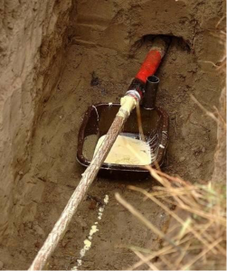
2.2 Sewer pipes
Wastewater networks provide wide coverage in many countries and can enable FTTH installation routes with reduced surface disruption. Sewer routes are typically deep and protected from many surface events.
The system must not interfere with wastewater flow, and materials must resist aggressive gases and contaminants. Installation also must avoid cleaning operations and mechanical hazards in the sewer line.
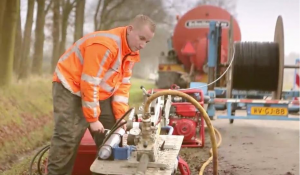
Figure 2: FTTH installation example: fiber cable can be blown into sewer systems using water pressure (approx. 10 bar) or pneumatic methods (up to ~12 bar), depending on system design.
2.3 Clean water pipes
Installing ducts or microduct paths via drinking water service routes has been explored in Europe using sealed adapters that create a gas-tight path so fibers can be introduced without direct contact with water.
Two approaches are commonly described: (1) adding sealed branch fittings at start/end points and routing a microduct between them, and (2) using building entry access with specialized jointing (e.g., electrofusion) to enable fiber routes to multiple buildings.

Figure 3: FTTH installation diagram for water pipe routing (sealed microduct concept).
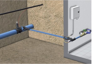
FTTH installation: duct containing the fiber optic cable enters the building inside a drinking water pipe.

Figure 5: Example connection concept for FTTH installation using drinking water pipe route (Adenau, Germany).
Both approaches can reduce installation cost by minimizing excavation, time, and surface restoration. Any component in contact with drinking water must comply with local regulations.
2.4 Gas pipes for houses
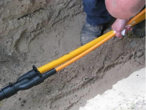
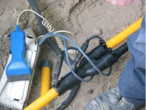
Residential gas service routes are another potential path, subject to strict national legislation, approvals, and material compliance. A dedicated duct can be inserted and fiber moved mechanically or by compressed air, depending on design.
This approach typically requires controlled access points and sealed integration methods (e.g., electrofusion welded fittings) to maintain gas-tight performance.
 |
 |
Section 6: Duct insertion concept via gas service tubing.
Section 7: Uniform, gas-tight link concept inside the pipe.
3. FTTH installation methods
3.1 Handheld fiber cable blowing machine
Traditional pulling creates high friction and exponential force build-up through bends (capstan effect). Blowing/jetting methods reduce these issues by using mechanical pushing plus airflow to support cable movement. For background terminology, see: Cable jetting (Wikipedia) and Cable blowing machine (Wikipedia).
In FTTH installation, especially with microducts and smaller cables, installers often need compact, controllable machines. Handheld or lightweight blowing machines can reduce crew size and speed up deployment, if duct prep, sealing, and lubrication are done correctly.

FTTH installation: compact fiber optic cable blowing machine example.
Figure 9: Handheld / compact fiber installation equipment used in FTTH installation.
Duct preparation, couplers, and sealing quality determine performance. The duct system must hold pressure without leakage. Connections and couplers must maintain internal diameter and seal consistently.
For branching duct connections or parallel blowing setups, Y connector for cable blowing machine can be used to distribute airflow safely without destabilizing installation.
Friction reduction is equally critical. Use a dedicated blowing lubricant (not generic pulling gel) for consistent distance and lower risk. Product reference: Cable blowing lubricant (UP-S-LUB-20).
If you want a full field procedure and engineering checklist approach (duct–cable pairing, airflow capacity, lubrication strategy, limits), see: Fiber Blowing Engineering Checklist.
3.2 Pushable fiber
Pushable fiber (and related blown fiber unit concepts) can reduce labor and field splicing, especially when used with pushable connectors. In some designs, a connectorized end can eliminate half the termination work.
Pushable fiber routes can be installed in otherwise “spent” pathways with no room for traditional ducts. A continuous sealed connection enables route continuity from outside plant to inside plant.
Section 10: Examples of pushable fiber assemblies used in FTTH installation.
3.3 Fiber optic cable de-coring
De-coring removes the internal core of certain legacy cables (copper/coax/power) to leave a usable sheath path without full excavation, enabling fiber replacement with reduced access points.
Section 11: Fiber optic cable de-coring in progress (path reuse concept).
4. Creative FTTH components
4.1 Flat micro-duct systems
Microducts are small conduits (typically ~7–20 mm OD ranges in many deployments) designed to carry micro cables efficiently. Flat microduct bundles can be twist-resistant, easier to place, and easier to branch in the field.
 Figure 12: Single thick-walled micro-ducts. |
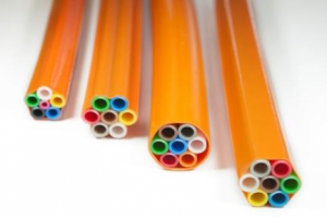 Figure 13: Micro-duct bundles in a round design. |

FTTH installation: creating a branch in a flat micro-duct system.
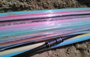
FTTH installation: flat micro-duct bundles installed in the ground.
4.2 Micro-ducts
Micro-duct systems allow telecom networks to split duct capacity into smaller protected pathways for micro cables, improving future scalability without repeated civil works. They can be installed inside larger ducts or delivered as bundled over-cased units for direct burial.
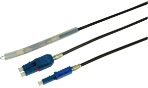
4.3 No epoxy, no polish connectors
Optical fiber termination traditionally relied on fusion splicing, mechanical splicing, or epoxy-and-polish connectors. New field-fit no-epoxy/no-polish (NE/NP) connectors aim to reduce time and tool dependency while keeping acceptable performance.
| Parameter | Fiber-fiber splice | Fiber-pigtail splice | Mechanical splice | Epoxy and polish |
| Performance | < 0.2 dB | < 0.5 dB | < 0.5 dB | < 0.5 dB |
| Skill level | High | High | Low | Medium |
| Time to joint | ~2 mins | ~2 mins | ~4 mins | > 5 mins |
| Capital investment | High | High | Low | Medium |
| Reliability | High | High | Medium | Medium |
| Product cost | Low | High | Medium | Low |
| Environmental resistance | High | High | Medium | Medium |
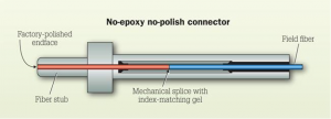
FTTH installation: no epoxy, no polish connector concept.
4.4 Pre-terminated fiber optic cable
When installation time is tight and labor cost is high, pre-terminated cable assemblies reduce field termination workload. In FTTH installation, drop cables with connectorized ends are common, but require careful stock planning to avoid waste and to manage slack length.
If your design includes high-density trunk connectivity, MPO/MTP concepts can become relevant in network design and data environments: What is MPO cable?
5. Creative project design
5.1 Case study: Parham, United Kingdom
Rural FTTH installation is expensive because premises are far apart and civil works per meter increase. In Parham (UK), a low-budget FTTH build used non-standard methods to reduce build cost and simplify customer connection.
5.2 Avoiding highways and associated costs
Avoiding road crossings and expensive highway permissions can dramatically reduce cost. Using land boundaries and field edges can minimize disruption and eliminate repeated traffic management expenses.
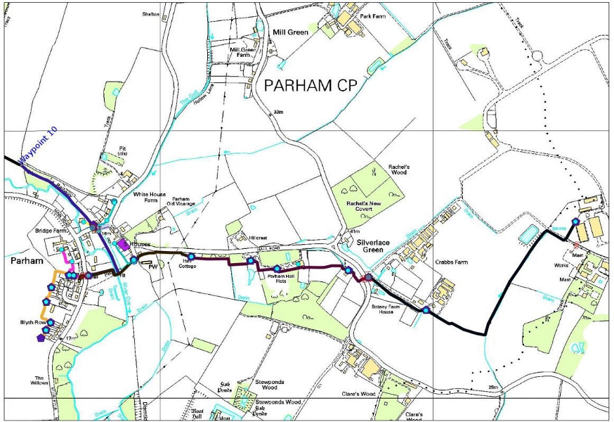
Figure 21: FTTH installation route following field boundaries (Parham, UK).
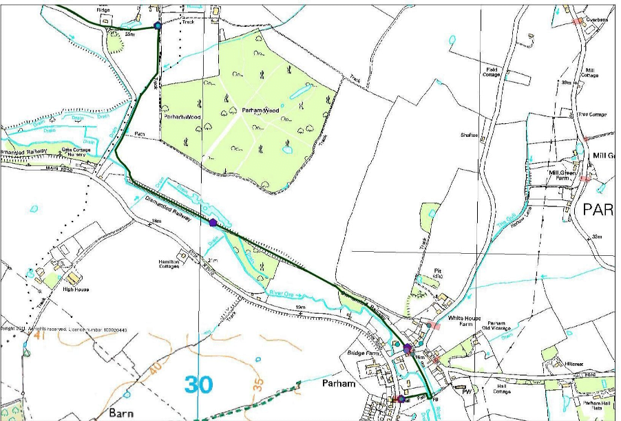
Figure 22: FTTH installation route using a disused railway alignment (Parham, UK).
5.3 Design for customer self-connection
Traditional models require return visits when customers sign up later. A “self-connect box” at the property boundary can reduce risk and reduce repeated field work on customer land.

FTTH installation: details of the customer self-installation.
Customer Install Pack (paid by customer): £250.00 – 282 Euro – ex VAT
| 1x 150ft Black Corrugated UV Stable duct |
| 1x 150ft QuikPush fiber optic cable (SC Terminated) |
| 1x Waterproof Connector |
| 1x Instruction Booklet |
| 1x SC clip-on connector |
| 1x ONT (Fiber Media Converter, Telephone Capable) |
| 1x Outdoor Wall Box |
| 1x Indoor Wall Box |
| 1x Patch Lead |
5.4 Cost breakdown of the Parham FTTH project
For this approach, total construction cost was reported at ~50% below a conventional expectation. The following breakdown shows example delivery equipment, fiber/microduct/closure equipment, and labor/civil works.
| Main Delivery Equipment: £29,990 – 33,800 Euro |
| 1 x Rack 36U with Power Distribution Unit |
| 1 x Uninterruptable Power Supply |
| 9 x 48 Port SC Fiber Patch Panels (with pigtails) |
| 1 x Cisco Catalyst Switch with line cards |
| 2 x Network Monitoring Computer |
| Optics, splitters, OLT chassis, batteries/rectifier, GPON cards, etc. |
If you want to connect this section to your product ecosystem, keep it clean and relevant: FTTH Deployment and Rack Cabinets.
Total install cost for 80 residents: £160,972 – 181,400 Euro
Abstract
- Use land boundaries instead of highways to reduce fees and civil works.
- Use local civil engineers and field contractors with simplified installation kits.
- Minimize splicing: splice only where it is technically necessary.
- Use the right method for the route: duct/microduct strategy, termination strategy, and installation equipment.
Conclusion
FTTH installation costs have fallen, but civil works still dominate many project budgets. Cost reduction comes from practical execution: infrastructure sharing, route design, microduct strategy, faster installation methods, and correct friction control.
If your goal is to speed up FTTH deployment in Europe, optimize “cost per meter” by reducing excavation, minimizing returns to site, and standardizing scalable duct/microduct architecture.
Related reading for importers and technical procurement teams: What Distributors Should Know Before Importing Fiber Optic Products .